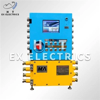
I. Inspection of Explosion-Proof Joints
1. Gap and Surface Treatment: Measure the gap of the explosion-proof joints using a feeler gauge. It must meet the standard (e.g., for Ex d type equipment, the gap ≤ 0.15mm). The surface should be smooth and free of scratches and rust. Cleaning is only permitted with kerosene and non-metallic scrapers; filing or sandpaper is strictly prohibited. After cleaning, apply a thin layer of anti-rust oil (e.g., type 204-1).
2. Fasteners and Sealing: Check that all housing bolts are complete and tight, ensuring the explosion-proof housing is free of deformation or cracks. The seals between pipes must be secure to prevent gas infiltration from hazardous areas.
II. Dust and Oil Cleaning and Heat Dissipation Maintenance
1. Daily Cleaning: Promptly remove dust and oil from the equipment surface to ensure unobstructed heat dissipation channels and prevent heat buildup that could cause surface temperatures to exceed limits. 2. Ventilation System Inspection: The heat sinks or forced air cooling devices of the explosion-proof enclosure must be cleaned regularly to ensure that the heat dissipation efficiency meets the requirements of the explosion-proof temperature rating.
III. Sealing Device and Cable Entry Inspection:
1. Explosion-proof Gland Maintenance: Check whether the clamping nuts of the cable entry device are loose and whether the sealing rings are aged to ensure explosion-proof sealing performance.
2. Intrinsically Safe Circuit Sealing: The cable entry device of intrinsically safe equipment must pass explosion-proof certification along with the enclosure. Arbitrary replacement or modification is prohibited.
IV. Intrinsically Safe Circuit Parameter Verification:
1. Safety Barrier Matching Verification: The following must be met: Safety barrier output parameters (Uo/Io/Po) ≤ intrinsically safe equipment input parameters (Ui/Ii/Pi), and external capacitance/inductance (Co/Lo) ≥ the sum of the internal equipment and line distributed parameters.
2. Cable Distributed Parameter Measurement: The cable distributed capacitance (Cc) and inductance (Lc) must be measured on-site to ensure that the total parameters do not exceed the safety barrier's allowable values. If the internal capacitance/inductance of the equipment exceeds 1% of the safety barrier's allowable value, the allowable cable length must be recalculated.
V. Anti-static and Grounding Inspection
1. Grounding Device Test: The anti-static grounding wire must be securely connected, with a grounding resistance ≤4Ω, to prevent static electricity accumulation from causing sparks.
2. Diode Safety Barrier Inspection: Ensure the safety barrier model is correct and the grounding rod is continuous and reliable to prevent intrinsically safe circuit failure.
VI. Maintenance Cycle and Records
1. Regular Professional Inspection: According to GB/T 3836.16-2017, monthly visual inspections and annual detailed inspections are required, including explosion-proof surfaces, electrical parameters, and sealing performance.
2. Maintenance Record Archiving: All inspections and repairs must be documented in a traceable file, including parameter test results and replaced component models.